One of the most appealing characteristics of the Oldham coupling is its simplicity: three parts, no lubrication required (in polymer-disc versions), and no adjustment mechanisms to drift out of calibration. This simplicity extends to its maintenance requirements. A properly specified and installed Oldham coupling demands very little attention — but “very little” is not the same as “none.” A structured maintenance approach, focused on the right inspection points at the right intervals, can extend coupling service life by a factor of two or more, and it can prevent the unplanned downtime that occurs when a worn coupling finally fails during production.
This guide covers everything needed to maintain Oldham couplings in service, from routine inspection through disc replacement to hub care and storage.
Why Maintenance Matters: The Wear Mechanism
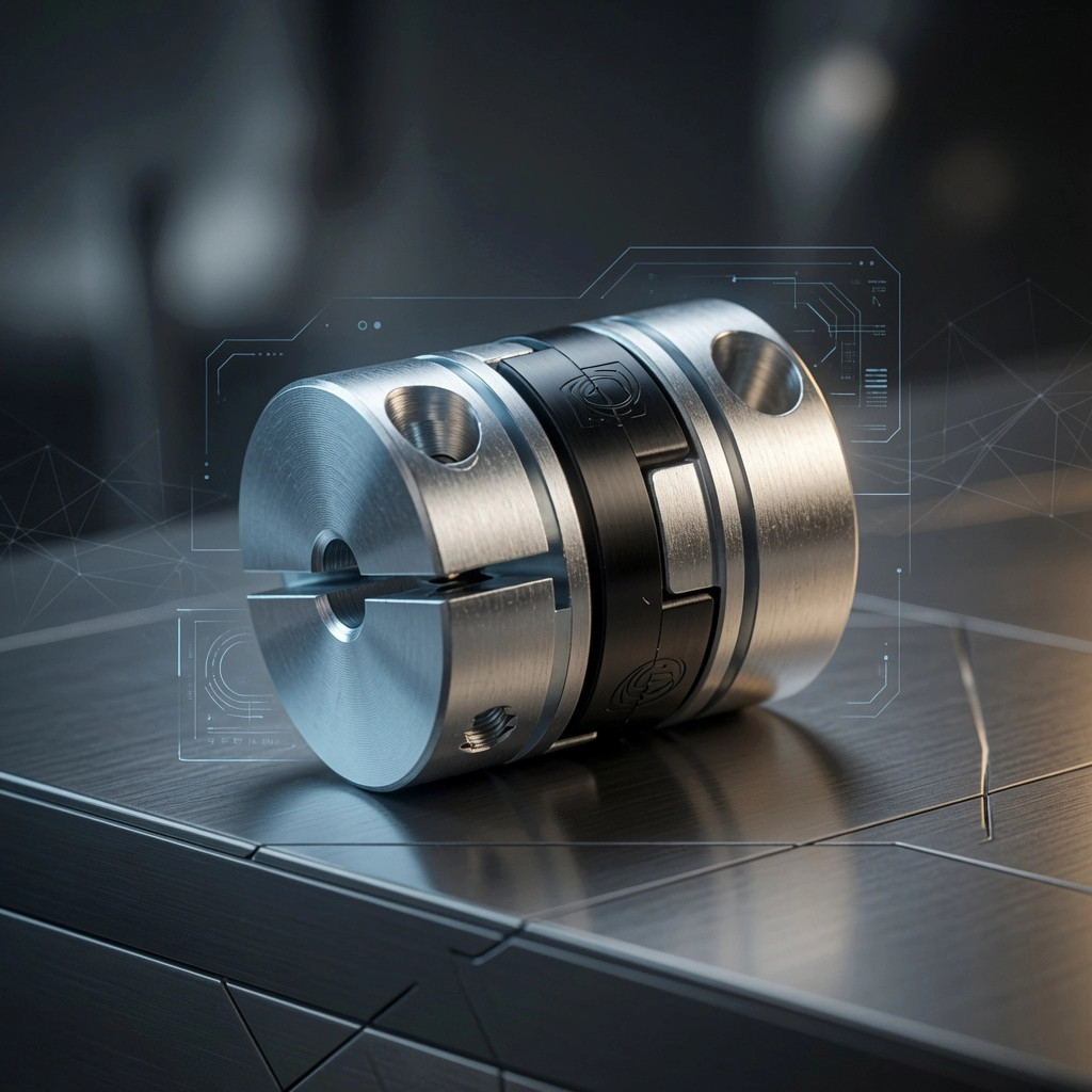
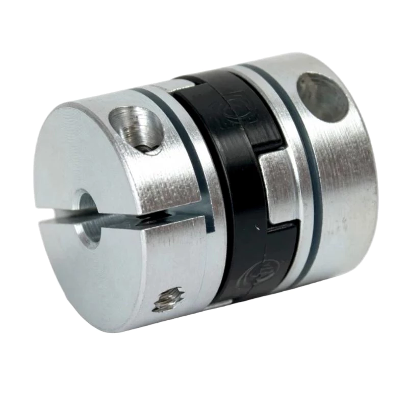
The Oldham coupling’s centre disc is in continuous sliding motion relative to the two hubs during operation. At every point in the rotation cycle, the disc tenons are sliding within the hub slots, with a sliding velocity and amplitude that depend on the shaft’s rotational speed and the lateral misalignment between the two shaft axes.
This sliding motion produces gradual surface wear on the disc tenon faces. In an acetal disc running within its rated parameters, this wear is slow and progressive — the disc can last for thousands of operating hours. However, wear is not zero. As the tenon faces lose material, the fit between tenon and slot becomes progressively looser, and the coupling develops a small but measurable amount of backlash. Once backlash appears, it typically accelerates: the loose fit allows impact loading at each reversal, which increases the wear rate further.
The maintenance objective is to detect and address wear before this acceleration phase begins — either by replacing the disc on a scheduled basis or by monitoring backlash and replacing the disc when it reaches a defined limit.
Establishing the Right Maintenance Interval
There is no universal maintenance interval for Oldham couplings because disc wear rate depends on several application-specific factors: rotational speed, lateral misalignment magnitude, transmitted torque, ambient temperature, and disc material. A coupling running at 500 RPM with 0.1 mm offset will outlast an identical coupling running at 3,000 RPM with 0.8 mm offset by a factor of twenty or more.
For new installations, the recommended approach is to establish an empirical interval through early monitoring:
- Measure and record backlash at commissioning (should be effectively zero for a new coupling)
- Re-measure at 500, 1,000, and 2,000 operating hours
- Plot the backlash trend against hours
- Set the replacement trigger at 50 percent of the maximum permissible backlash level, and schedule replacement accordingly
Once a replacement interval is established for a given application, it can be incorporated into the machine’s planned maintenance schedule. For most precision motion applications with acetal discs, intervals of 2,000 to 8,000 operating hours are typical, depending on speed and misalignment.
Backlash Measurement: The Key Diagnostic
Backlash is the primary diagnostic metric for Oldham coupling condition. It is easy to measure, requires no specialist equipment, and provides a direct indication of remaining disc service life.
Method 1 — Dial indicator at the load: Fix a dial indicator against the driven component (ballscrew nut, gear, sprocket). Hold the driving shaft stationary and manually rotate the driven shaft back and forth. The indicator reading is the total coupling backlash in linear terms at the measurement radius. Convert to angular units if needed: backlash (degrees) = (linear reading / measurement radius) × (180 / π).
Method 2 — Direct angular measurement: Clamp a pointer to each hub. Rotate the driving hub clockwise until resistance is felt, then mark the driven hub position. Rotate the driving hub anti-clockwise until resistance is felt again, and re-mark. The angular difference between the two driven hub marks is the backlash. For precision measurements, use a circular protractor or digital angle gauge.
As a general guideline, replace the disc when measured backlash exceeds 0.3 degrees, or when the manufacturer’s wear limit is reached, whichever is lower. For very high-precision applications such as encoder drives, the threshold may be tighter — 0.1 degrees or less.
Centre Disc Replacement Procedure
One of the Oldham coupling’s most significant maintenance advantages is the speed and simplicity of disc replacement. The hubs do not need to be removed from their shafts — the disc can be exchanged in five minutes or less on most installations.
Step 1 — Isolate and lock out the machine. Follow your facility’s lockout/tagout procedure. The coupling must not be serviced while the drive system is energised.
Step 2 — Loosen the hub fasteners. Do not remove them fully — loosen just enough to allow each hub to slide axially along its shaft. For clamp hubs, loosen the clamping screw until the bore is free. For set-screw hubs, back the screw out two to three turns.
Step 3 — Separate the hubs axially. Slide each hub a few millimetres away from the centre disc. There is no need to move them far — just enough to disengage the disc tenons from the hub slots.
Step 4 — Remove the worn disc. Lift the disc out from between the two hubs. Inspect it: note the wear pattern on each tenon face, any cracking, and whether wear is symmetrical. This inspection takes ten seconds but provides valuable information about whether the coupling is operating within its design parameters.
Step 5 — Inspect hub slots. With the disc removed, examine the slot walls of both hubs under good lighting. They should be flat and square with clean edges. Any rounding, scoring, or embedded debris indicates hub wear that should be addressed before reinstalling a new disc.
Step 6 — Install the new disc. Engage one face’s tenon into one hub’s slot. Slide that hub back toward its operating position, then engage the other face’s tenon into the second hub’s slot. Ensure both tenons are fully seated in their respective slots.
Step 7 — Restore hub positions and tighten fasteners. Slide each hub back to its original axial position (check that the disc is not being compressed axially between the hubs — there should be a small clearance). Tighten hub fasteners to the manufacturer-specified torque using a calibrated torque tool.
Step 8 — Verify backlash. Before returning the machine to service, perform a quick backlash check. A new disc should restore the coupling to effectively zero backlash.
Hub Care and Long-Term Preservation
While the centre disc is the wear element, the hubs are designed to last the life of the machine — provided they are properly maintained.
Slot cleaning: After removing a worn disc, clean the hub slots with a dry lint-free cloth to remove any debris or disc material fragments. Do not use abrasive materials or wire brushes on aluminium hubs, as this can damage the slot geometry.
Bore care: The hub bore is the most critical surface for coupling concentricity. Never use tools that can scratch or deform the bore surface. If fretting corrosion (reddish-brown oxide deposit) is observed in the bore, clean it with a fine abrasive cloth, then apply a thin film of anti-fretting compound before reinstalling.
Fastener condition: Check that clamping screws and set screws are in good condition at each disc replacement. Replace any fastener that shows thread damage, cross-threading, or a deformed head that prevents accurate torque measurement.
Corrosion inspection: Standard aluminium hubs develop a protective oxide layer that prevents further corrosion in most environments. However, in acidic or salt-spray environments, more aggressive corrosion can develop. Inspect hub surfaces at each disc replacement and address any signs of pitting or surface degradation.
Alignment Check at Disc Replacement
Disc replacement is an excellent opportunity to re-verify shaft alignment, because the coupling is partially disassembled and the shaft axes are accessible for measurement. Improved alignment directly reduces disc wear rate and extends the service interval for the new disc.
With the hubs loosened and the disc removed, mount a dial indicator on one shaft and sweep it around the other shaft’s hub bore or a reference surface concentric with the shaft axis. Read the total indicator runout (TIR). For precision motion applications, aim for TIR below 0.1 mm. If TIR exceeds 0.2 mm, adjust the motor mounting before reinstalling the new disc.
Also verify that the two shaft ends are at the correct axial separation to allow the coupling to function within its axial float specification. The disc should sit freely between the hubs without axial compression.
Replacement Disc Storage and Shelf Life
Replacement discs should be stored in a cool, dry location away from direct sunlight and sources of ozone (including electric motors, welding equipment, and UV lamps). Ozone and UV radiation accelerate degradation of polymer materials, even acetal, reducing the hardness and wear resistance of the disc material before it is ever installed.
Store discs in their original packaging or in sealed plastic bags. Keep them away from lubricants and solvents — even vapour-phase chemical exposure can affect the surface properties of acetal and nylon over time. Properly stored acetal discs have an effective shelf life of five years or more.
Before installing a disc from storage, inspect it for any visible degradation — surface cracking, discolouration, or dimensional distortion. A disc that shows any of these signs should not be installed, even if it has never been used.
Maintenance Record Template
Keeping a simple maintenance log for each Oldham coupling in service costs very little time but provides valuable data for optimising replacement intervals and identifying application issues. Record the following at each inspection and disc replacement:
- Date and machine operating hours at inspection
- Measured backlash (degrees or arc-minutes)
- Disc condition on removal: wear only, fracture, chemical degradation, or unusual wear pattern
- Hub slot condition: good, minor wear, or significant wear requiring hub replacement
- Shaft alignment TIR at this inspection
- Action taken: disc replaced, hub replaced, alignment adjusted, or no action
- New disc part number and material
Conclusion
Oldham coupling maintenance is not complex, but it does require regularity. The investment is small — periodic backlash measurement, a five-minute disc replacement when wear reaches its threshold, and occasional hub cleaning and alignment verification. The return on that investment is a coupling that consistently delivers zero-backlash performance throughout its service life, extends machine accuracy and bearing life, and never causes an unplanned production stoppage because a worn disc was left in service too long.
Browse our replacement disc and coupling catalogue, or contact our team to discuss maintenance strategies for your specific application.


